Table of Contents
Doppler wind lidar

HALO Photonics Doppler wind lidar at JOYCE
The doppler wind lidar has been out of operation since January 2025. It is currently unclear whether it can be repaired.
Principle
The backscattered light from an emitted laserbeam is used to measure wind speed. Analysis of doppler shift gives wind speed along the beam. Combination of several beams allows an estimate of the three components of the wind vector. Amount of received backscattered light allows calculation of backscatter coefficient.
Measurement modes
- Vertical staring mode (1.67 seconds temporal resolution)
- Full azimuth and elevation scan capability
JOYCE-CF Standard Operation Procedures
The instrument performs several scanning patterns and uses the remaining time for vertical staring.
Scan patterns are currently:
- Every 5 minutes doppler beam swinging (DBS) (12×14sec/hour=2min48sec/hour), i.e. one vertical and two tilted beams in eastern and western direction to derive instantaneous local wind profiles
- Directly followed by a 3 beam VAD (VAD-3) (12×14sec/hour=2min48sec/hour), i.e. three tilted beams in at 0, 120 and 240 deg azimuth and 30deg zenith distance to derive instantaneous local wind profiles
- Every 15 minutes a velocity azimuth display scan (VAD-36) (4×124sec/hour=8min16sec), i.e. a conical scan at 75oelevation to derive area averaged wind profiles
- Every 60 minutes a range height indicator (RHI) (1×10⁴sec/hour=1min44sec/hour), i.e. a vertical section from east to west with 5deg elevation steps (37beams)
- The rest of the time is vertical staring, i.e. vertical staring is interrupted every 5 minutes and sums up to 47minutes/hour
Data availability
Most of the following data products are provided via the SAMD database. If you would like to have additional data or recent data that have not been uploaded to SAMD yet, please fill the data request sheet and send it to info@joyce.cloud
| Dataset | Temporal resolution | File size | Filename | Retrieval / Remarks |
|---|---|---|---|---|
| Vertical stare data (Backscatter, Doppler velocity) | 2 seconds | 1 file per day (180 MB) | sups_joy_dlidST00_l1_any_v00_YYYYMMDDHHMMSS.nc | available on SAMD |
| 3D wind profiles from custom scanning | 5 minutes | 1 file per day (3.3 MB) | sups_joy_dlidCUST00_l2_wind_v00_YYYYMMDDHHMMSS.nc | available on SAMD |
| 3D wind profiles from Doppler beam swinging | 5 minutes | 1 file per day (3 MB) | sups_joy_dlidDBS00_l2_wind_v00_YYYYMMDDHHMMSS.nc | available on SAMD |
| Mixing layer height from vertical velocity | 5 minutes | 1 file per day (180 MB) | sups_joy_dlidST00_l2_zmlaw_v00_YYYYMMDDHHMMSS.nc | available on SAMD |
| 3D wind profiles from VAD-36 | 15 minutes | 1 file per day (1.6 MB) | wind_vad-36_YYYYMMDD.nc |
Link to current observations
Current observations at quicklook archive
Measurement examples
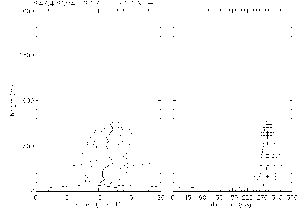
Current wind profile:
Current VAD plot:
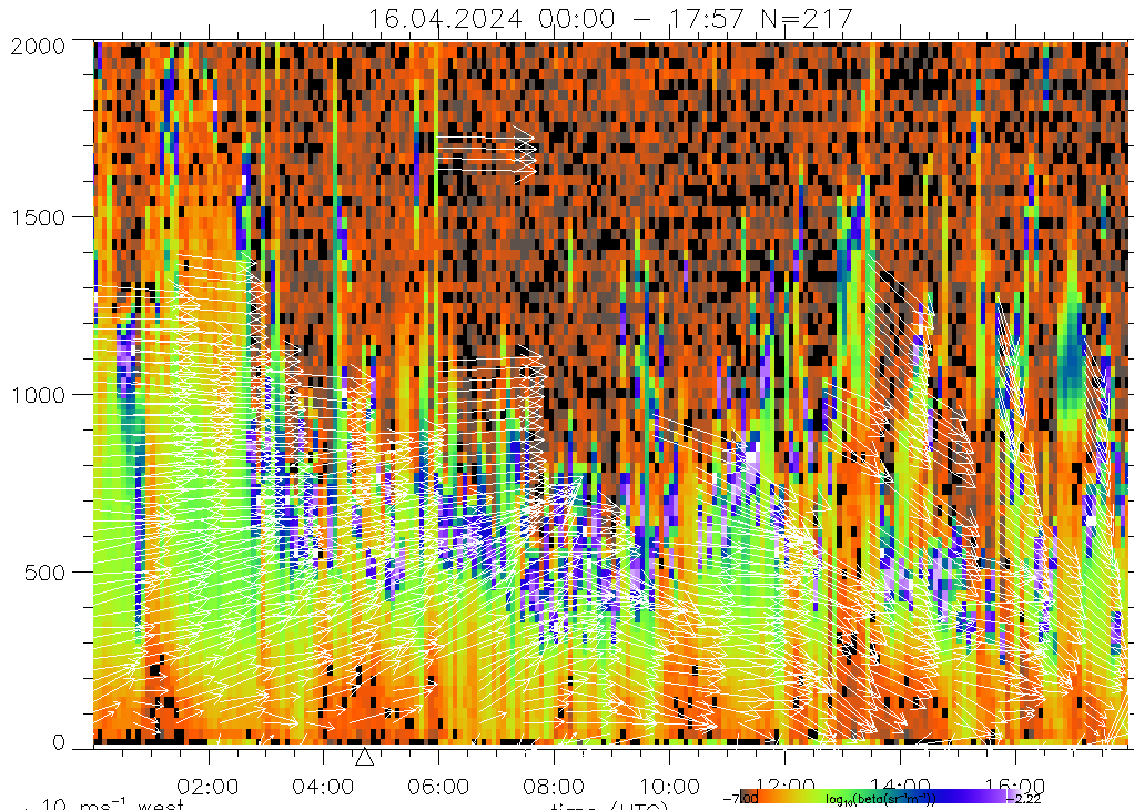
The figure shows a velocity azimuth display (VAD): vectors give direction and speed of horizontal wind at time and height. Vectors pointing upward indicate southerly winds, vectors pointing to the right indicate westerly winds. Color shading gives the backscatter coefficient.
Doppler lidar History
| Period | Place | Project |
|---|---|---|
| 12.9.2012 - 22.01.2025 | Research Center Jülich, Germany | TR32 |
| 26.7.2012 - 31.8.2012 | Engelsdorf, Germany | TR32-patvap |
| 7.11.2011 - 26.7.2012 | Research Center Jülich, Germany | TR32 |
Technical specifications
| Parameter | Specification | Remark |
|---|---|---|
| Wavelength / nm | 1500nm | |
| Pulse energy / $\mu$J | ~100 | see ARM Doppler lidar handbook |
| Pulse width / ns (m) | 150 (22.5) | see ARM handbook |
| Repetition Rates / s | 1/15000 | i.e. 15000 laser pulses per second (=Pulse repetition frequency PRF) |
| 1.67 | avg.beam i.e. N_avg pulses averaged and processed ⇒ dead time=0.67s | |
| 300 | Doppler Beam swing (DBS) with 3 beams ([azi,ele] = [0,90],[0,75],[90,75]) | |
| 900 | Velocity azimuth display (VAD) with 36 beams ([azi,ele] = [i*10,75]) | |
| 3600 | vertical slice (RHI) with 18 beams ([azi,ele] = [109,i*10]) | |
| N_avg | 15000 | number of pulses to be averaged in one 'beam' |
| resolution / m | 30 | range resolution (adjustable from 15m onward) |
| Field-of-View / deg | 360 x 90 | free alingment of the beam |
| maximum range / m | 9000 | adjustable, but restriced to sufficent backscatter (aerosol, cloud droplets or ice crystals) |
| velocity resolution / ms-1 | 0.0382 | adjustable |
| velocity precsision / ms-1 | < 0.20 | for SNR > -17dB |
| max velocity / ms-1 | 19.2 | = Nyquist Velocity (adjustable) |
| Aperture / mm (area /m2) | 75 (4.417e-3) | see ARM handbook |
| Size / cm³ | 80 x 53 x 40 | |
| Average Power consumption / W | 140/250 [600] | (wo/w Heating/cooling) [The power supply shall provide 600W] |
| Weight / kg | 110 | with transport case |
| Manufacturer | Halo Photonics | |
| Year | 2011 | |
| Instrument | streamline Instrument #17, XR version in 2010, 15kHz PRF, 10km max range |